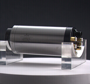

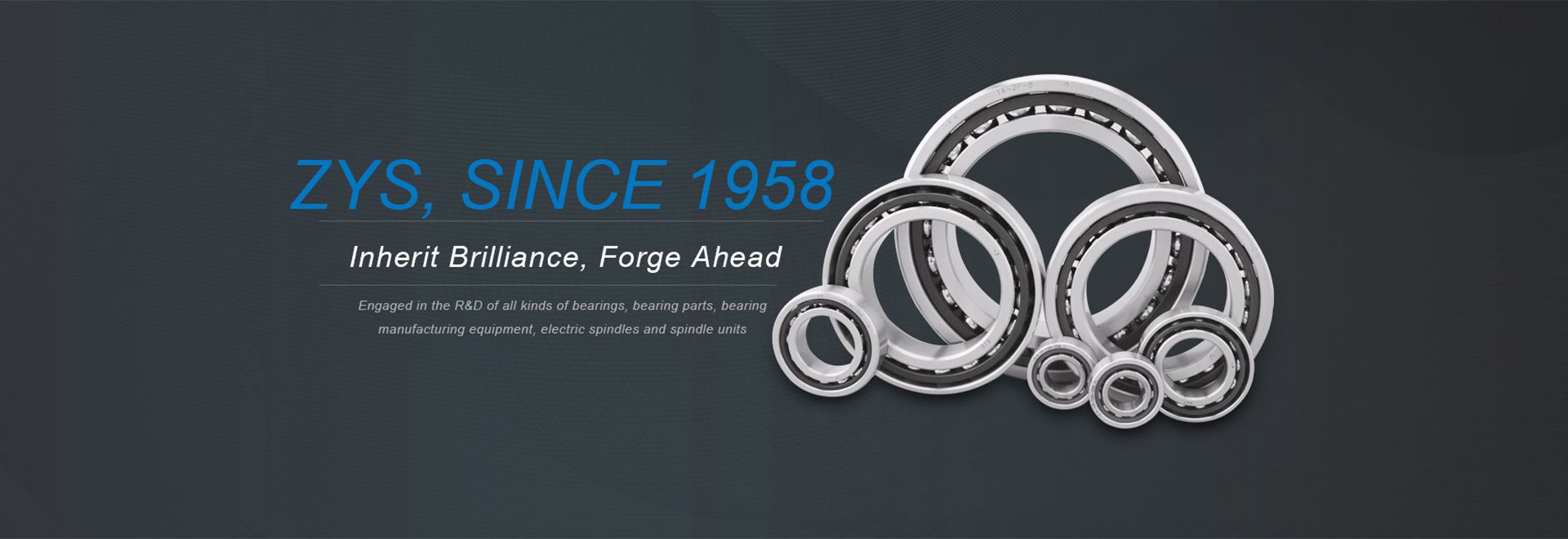
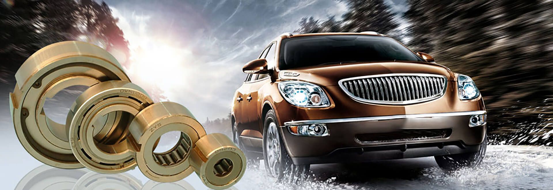
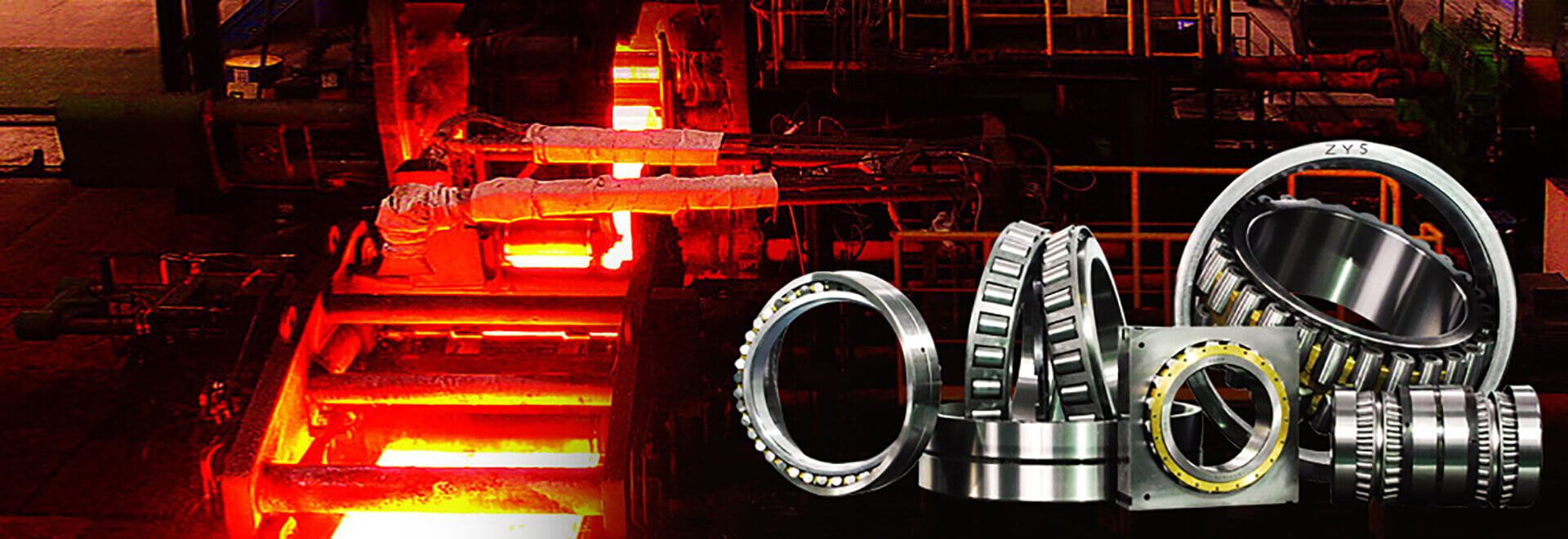

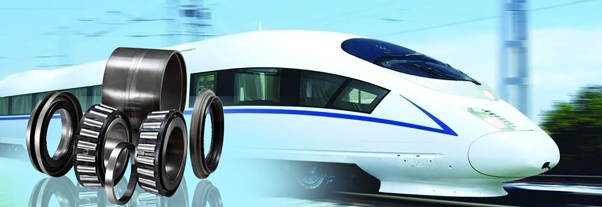
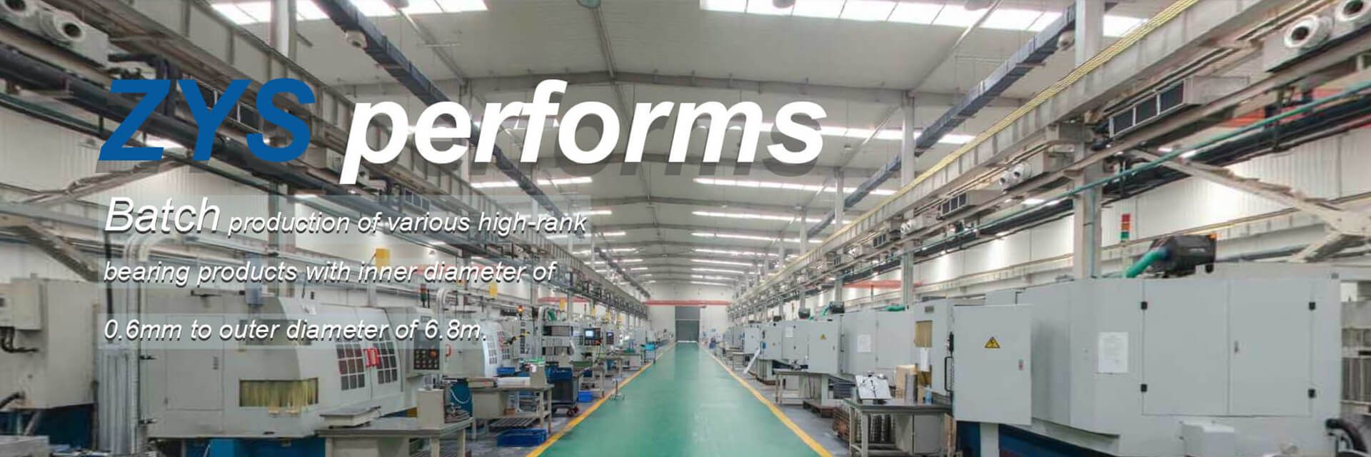
ZYS provides high quality bearing products and professional bearing solutions for users in the fields of machine tool, wind power, metallurgy, automobile and rail transportation, construction machinery, etc. ZYS can perform batch production of various bearing products with inner diameter of 0.6mm to outer diameter of 6.8m. In addition to bearings, ZYS can also offer high-speed spindles, precision bearing instruments, bearing testing machines, bearing manufacturing machines and bearing parts.
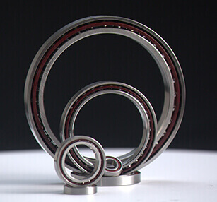
ZYS precision angular contact ball bearings consist of high-precision angular contact bearings (standard series),super high-speed angular contact ball bearings,high-speed sealed angular contact ball bearings and high-speed spindle bearings.
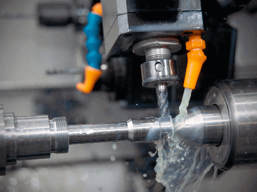
In the metallurgical industry, the working environment of rolling mills, continuous casting machine or converters is really harsh. These conditions require bearings to withstand the harsh effects of heavy load, high temperature, dust and water. In order to meet the requirements of metallurgical industry, ZYS R & D teamhas developed bearings products with high quality, high precision and long service life and also can offer the bearing solutions for manufacturers in the metallurgical industry.
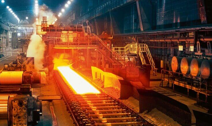
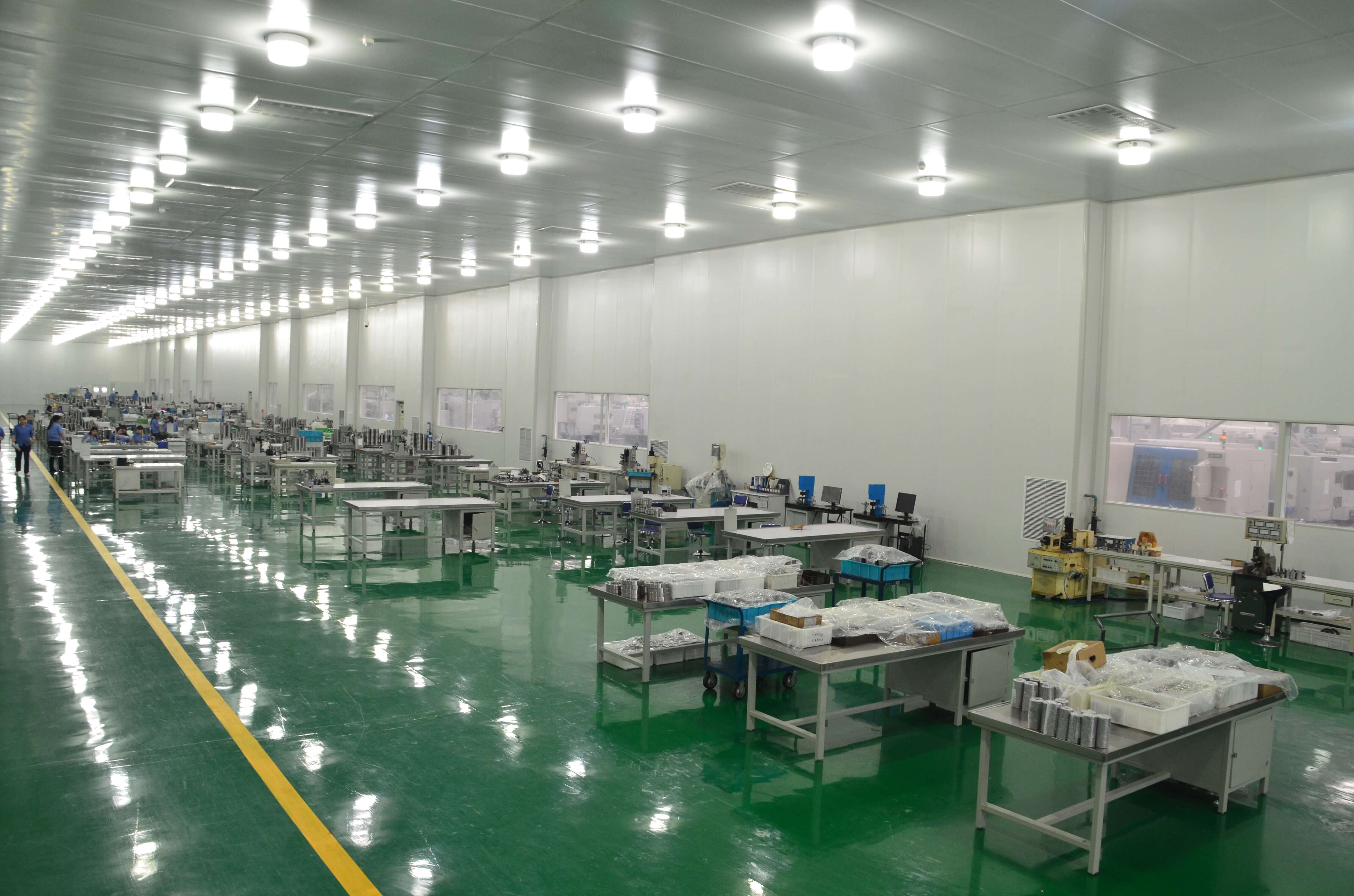
ZYS large-size heavy duty precision bearings are manufactured in our second industry park,which covers 133,333㎡ with total investment of 438 million RMB.
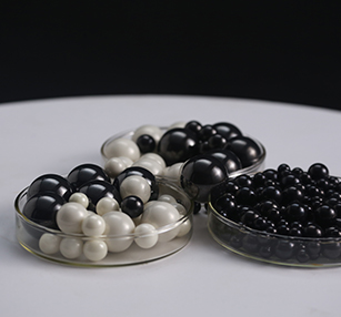
The inner ring,outer ring and rolling elements of bearing under normal working conditions are made of high carbon chromium bearing steel.To meet the special requirements,such as super high speed,wear-resisting,low temperature rising,long life and high reliability etc.,it’s suggested to use hybrid ceramic ball bearings.
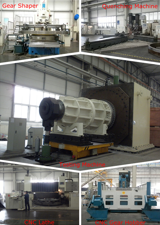
ZYS has been committed to the research and development of bearings for rail transportation for a long time to meet the increasing requirements for rail transportation,such as higher speed,load,reliability and etc.
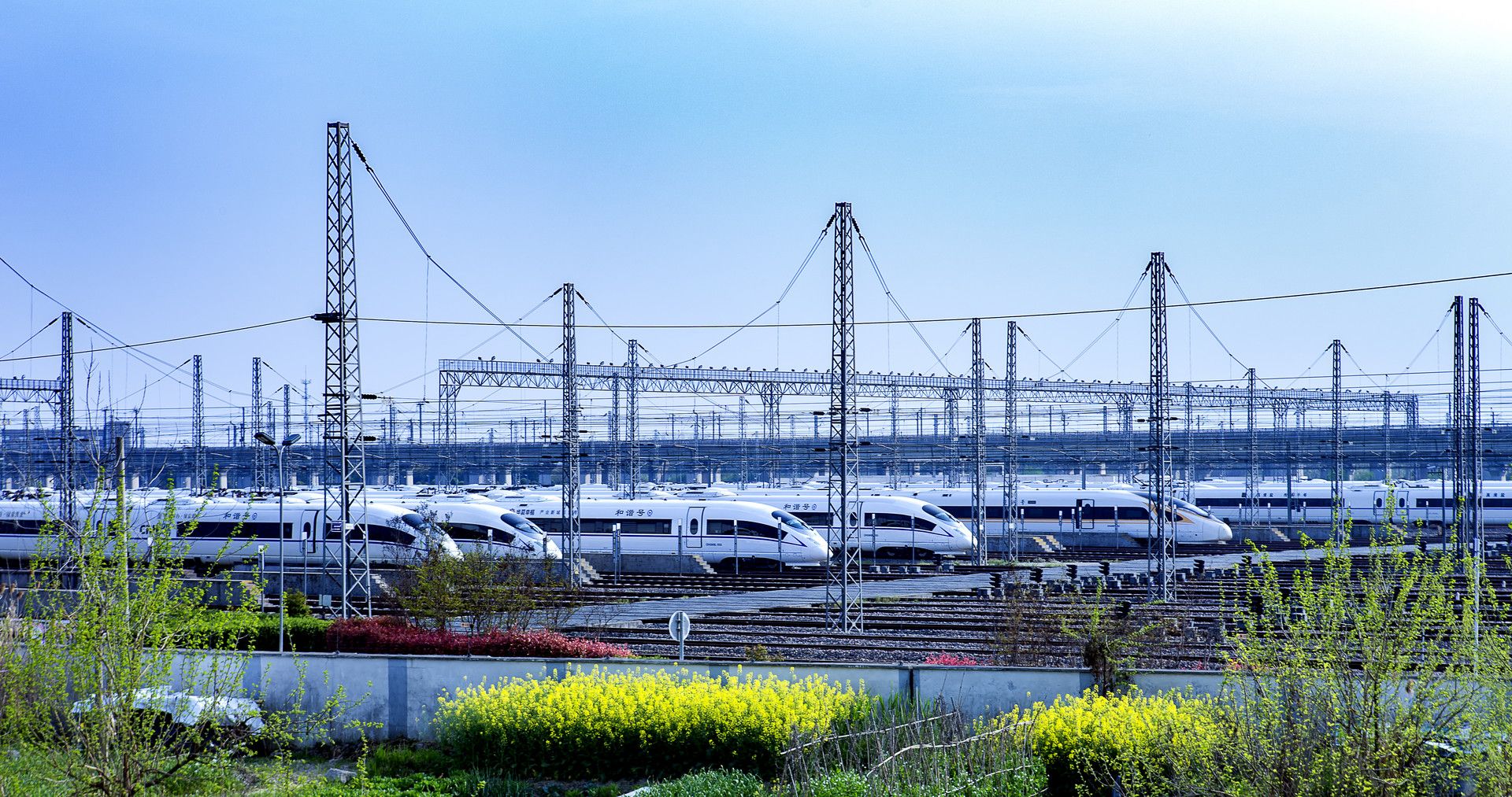
ZYS plays an leading role in aerospace bearing industry of China,We has successfully accomplished the bearing assemblies for “Dong fang hong” series man-made satellite,manned spacecraft series from “Shenzhou Ⅰ” to “Shenzhou Ⅹ”,“Chang’E” lunar exploration program,successful docking from “Shenzhou Ⅷ” and “Shenzhou Ⅸ” to Tiangong target aircraft.

ZYS automobile bearings include tapered roller bearings,cylindrical roller bearings,deep groove ball bearings and angular contact ball bearings,among which clutch bearings and the hub bearings units of the first,second and third generation are mainly used to gear box,axles,transmission system and other parts of all kinds of automobiles.We have conducted thorough research on wheel hub bearings,clutch release bearing,constant velocity cardan joint,gear box bearings and etc

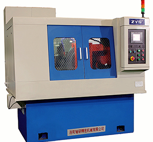
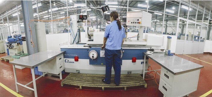
ZYS can supply batch production of various bearing manufacturing equipments,like CNC cutting equipments and automatic production line for bearing rings,automatic grinder,superfinishing machine,precision cold rolling machine for bearing rings,semi-automatic multi-purpose grinder for miniature ball bearing rings and other precision manufacturing equipments for bearing.
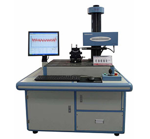
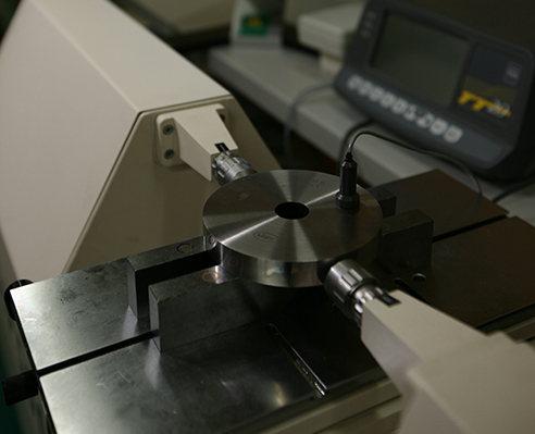
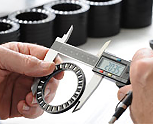
Besides all kinds of bearing products,bearing measuring machines are also our main products,which have been exported to India,Iran,Romania,Brazil and many other countries.Our main measuring machines include the instruments for measuring the dimension accuracy,roundness,profile and roughness of bearing parts,the instruments for inspecting bearing performance and other instruments used to automatically inspect and control various parameters during manufacturing process.These instruments are widely used in bearing workshops,inspection stations,measuring room and assembly factories.
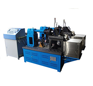
ZYS has conducted in-depth research on bearing testing technology and reliability theory of all kinds of bearings,engaging in the development and manufacture of bearing testing equipments and undertaking the simulation testing,life testing and other performance tests for all kinds of bearings.We can also develop and manufacture the simulation testing machines in full-automatic control for the bearings used in various machineries (aviation,spaceflight,railway,automobile,motorcycle,machine tool,motor,etc.)
Since 1958, ZYS has been committed to the research and development of “high-tech, precise, cutting-edge, specialized and special” bearings, and relevant products. Our products have been used for mining, metallurgy, wind turbine generator, machine tool, machinery, medical treatment, automobile, rail transport, etc.

1. What Is Cold Rolling in Bearing Manufacturing?Cold rolling is a metal forming process that uses pressure to cause plastic deformation in a metal workpiece, typically at or near room temperature. In bearing manufacturing, cold rolling can be used to form ring-shaped workpieces by controlling the deformation of the material through rolling tools.Unlike conventional machining, which removes material through cutting, cold rolling reshapes the workpiece primarily through plastic deformation. For suitable applications, this process can help optimize blank geometry and reduce the amount of material removed during subsequent machining.Cold rolling does not necessarily eliminate subsequent machining operations. Depending on the bearing design and manufacturing requirements, bearing rings may still require turning, heat treatment, grinding and other finishing processes to achieve the specified dimensional accuracy, geometric tolerances and surface quality.The effectiveness of cold rolling depends on material properties, blank geometry, tooling design, forming conditions and subsequent manufacturing processes.2. How Does the Cold Rolling Process Work?The basic principle of cold rolling is to apply controlled pressure through rolling tools, causing the workpiece to undergo plastic deformation. For ring-shaped components, the process aims to achieve the required geometry through controlled material flow rather than relying entirely on material removal.Several factors influence the forming process:Material properties and initial conditionBlank dimensions and geometryRolling force and feed rateTool design and contact conditionsProcess monitoring and controlSubsequent heat treatment and finishing operationsIn bearing ring production, appropriate control of these factors is essential for achieving consistent forming results. The process must be developed and validated according to the specific bearing design, material and production requirements.3. Key Features of a Cold Rolling MachineA cold rolling machine for bearing manufacturing integrates mechanical structures, rolling tools, loading mechanisms and control systems to perform the required forming operations.3.1 High-Rigidity Mechanical StructureStructural rigidity is important in cold rolling equipment because the machine must withstand the loads generated during forming. A rigid mechanical structure helps maintain stable operating conditions and supports process consistency.Symmetrical shaft support arrangements can contribute to structural stability under working loads. Actual machine performance depends on the overall structural design, component quality and operating conditions.3.2 Dual Stations for Rolling and SizingA dual-station configuration combines rolling and sizing functions within one machine.The rolling operation produces the required plastic deformation, while sizing helps control the final dimensions of the workpiece. The operating sequence and coordination of the two stations depend on the machine configuration and selected process.Integrating these functions into one equipment configuration can simplify process coordination, although the actual effect on productivity depends on the workpiece and production conditions.3.3 Active Measurement and Process MonitoringActive measurement technology can provide dimensional information during processing, allowing relevant parameters to be monitored and controlled.A magnetoelectric detection system may also be incorporated into the machine design. The measurement range, accuracy, response characteristics and control functions depend on the specific system configuration and should be verified in the equipment documentation.Effective process monitoring helps manufacturers identify deviations and maintain more consistent operating conditions.3.4 Hydraulic Proportional LoadingHydraulic systems provide the loading force required for forming operations. Proportional hydraulic control allows the loading process to be adjusted according to process requirements.Appropriate control of loading is important for managing material deformation. The available control functions and achievable performance depend on the hydraulic system, machine configuration and process parameters.3.5 PLC-Based Electrical ControlA programmable logic controller (PLC) coordinates the relevant machine operations and control sequences.Depending on the configuration, computer-based process monitoring, active measurement and proportional servo control may also be integrated. These functions support coordinated operation and process management, but their specific capabilities should be confirmed for the selected machine model.3.6 Workpiece RoundingA rounding device can help control the geometry of the workpiece during rolling.Roundness is an important geometric characteristic of bearing rings. The final result depends on the initial blank, tooling, process parameters and machine condition. Appropriate dimensional inspection is necessary to verify that the processed workpiece meets the required specifications.4. Potential Benefits of Cold Rolling in Bearing Production4.1 Reduced Material RemovalCold rolling changes the geometry of a workpiece through plastic deformation rather than relying solely on cutting. For suitable workpieces and process conditions, this can reduce the amount of material removed during subsequent machining.Actual material savings depend on blank design, forming allowance, required final dimensions and the downstream machining route.4.2 Improved Blank GeometryWith appropriate tooling and process control, cold rolling can help produce blanks with geometry suitable for subsequent manufacturing operations.However, cold rolling alone does not guarantee that the finished bearing ring will meet its final dimensional tolerances. Additional machining, finishing and inspection may still be necessary.4.3 Potential Manufacturing Efficiency ImprovementsCombining rolling and sizing operations within one machine configuration may help coordinate forming operations and reduce unnecessary handling between process stages.Whether the process improves production throughput or reduces manufacturing costs depends on cycle time, equipment utilization, workpiece characteristics and the overall production route. These benefits should be evaluated using application-specific trials and production data.4.4 Material Structure and Mechanical PerformanceCold plastic deformation can influence a metal's strain distribution, residual stress and microstructure. The resulting changes depend on material composition, initial microstructure, deformation level and subsequent heat treatment.Therefore, improvements in strength, fatigue performance or bearing service life should not be assumed solely from the use of cold rolling. Such outcomes require appropriate material characterization and performance testing.5. Technical Specifications of the ZYS Cold Rolling MachineThe following table presents the technical specifications published for the ZYS cold rolling machine.ParameterSpecification 1Specification 2Specification 3Specification 4Rolling force (kN)80120200240Maximum outer diameter (mm)72100120160Minimum inner diameter (mm)202560100Maximum width (mm)25404560Spindle speed (r/min)100160160140Feed rate (mm/s)0–1000–300–300–6Main motor power (kW)5.57.51522Hydraulic motor power (kW)34/5.54/7.54/7.5Lubricating oil capacity (L)2222Hydraulic oil capacity (L)160250250250Rolling oil capacity (L)100120120120Height (mm)1,5001,9501,8002,000Weight (kg)2,6004,0005,0005,500For equipment selection, confirm the complete specifications, configuration and applicable operating range with the manufacturer.6. How to Select a Suitable Cold Rolling MachineSelecting a cold rolling machine requires more than comparing maximum dimensions and rolling force. The following factors should be considered.6.1 Workpiece DimensionsConfirm the outer diameter, inner diameter and width of the bearing ring blank. Check these dimensions against the applicable machine specifications and verify that the required workpiece geometry can be accommodated.6.2 Material and Initial Blank ConditionMaterial composition, mechanical properties and initial condition influence plastic deformation behavior. The suitability of the material for the proposed process should be evaluated before selecting the equipment and establishing process parameters.6.3 Forming RequirementsConsider the required geometry, deformation level, dimensional consistency and production volume. Rolling force, feed rate, tooling arrangement and control functions should be evaluated together to determine whether the machine is suitable for the application.6.4 Measurement and Control CapabilitiesFor applications requiring consistent forming results, verify the capabilities of the active measurement system, electrical controls and hydraulic loading system. Confirm the applicable measurement range, control functions and operating limits in the technical documentation.6.5 Integration with Subsequent Manufacturing OperationsCold rolling is one stage of the bearing manufacturing process. Equipment selection should account for compatibility with subsequent operations, including turning, heat treatment, grinding and inspection, as required by the bearing design.Before finalizing the equipment selection, provide the manufacturer with workpiece drawings, material specifications, quality requirements and target production volumes. Technical consultation and process trials can help determine whether the proposed configuration is suitable.7. ConclusionCold rolling is a metal forming technology that can be applied to bearing ring manufacturing. With appropriate process design, suitable tooling, a stable mechanical structure and effective process monitoring, it can help improve blank geometry and reduce material removal during subsequent machining operations.The practical benefits depend on workpiece design, material condition, process parameters, machine configuration and downstream manufacturing requirements. Careful equipment selection, process validation and quality inspection are essential for achieving consistent results.The ZYS cold rolling machine incorporates rolling and sizing functions, active measurement, hydraulic loading and PLC-based control. For bearing manufacturers evaluating cold rolling equipment, the key is to match machine capabilities with actual workpiece dimensions, material properties and production requirements.
2026-10-19 16:57:23 moveCold Rolling of Bearing Rings: Working Principles, Machine Design and Process Benefits
2026-10-19 16:57:231. What Is Cold Rolling in Bearing Manufacturing?Cold rolling is a metal forming process that uses pressure to cause plastic deformation in a metal workpiece, typically at or near room temperature. In bearing manufacturing, cold rolling can be used to form ring-shaped workpieces by controlling the deformation of the material through rolling tools.Unlike conventional machining, which removes material through cutting, cold rolling reshapes the workpiece primarily through plastic deformation. For suitable applications, this process can help optimize blank geometry and reduce the amount of material removed during subsequent machining.Cold rolling does not necessarily eliminate subsequent machining operations. Depending on the bearing design and manufacturing requirements, bearing rings may still require turning, heat treatment, grinding and other finishing processes to achieve the specified dimensional accuracy, geometric tolerances and surface quality.The effectiveness of cold rolling depends on material properties, blank geometry, tooling design, forming conditions and subsequent manufacturing processes.2. How Does the Cold Rolling Process Work?The basic principle of cold rolling is to apply controlled pressure through rolling tools, causing the workpiece to undergo plastic deformation. For ring-shaped components, the process aims to achieve the required geometry through controlled material flow rather than relying entirely on material removal.Several factors influence the forming process:Material properties and initial conditionBlank dimensions and geometryRolling force and feed rateTool design and contact conditionsProcess monitoring and controlSubsequent heat treatment and finishing operationsIn bearing ring production, appropriate control of these factors is essential for achieving consistent forming results. The process must be developed and validated according to the specific bearing design, material and production requirements.3. Key Features of a Cold Rolling MachineA cold rolling machine for bearing manufacturing integrates mechanical structures, rolling tools, loading mechanisms and control systems to perform the required forming operations.3.1 High-Rigidity Mechanical StructureStructural rigidity is important in cold rolling equipment because the machine must withstand the loads generated during forming. A rigid mechanical structure helps maintain stable operating conditions and supports process consistency.Symmetrical shaft support arrangements can contribute to structural stability under working loads. Actual machine performance depends on the overall structural design, component quality and operating conditions.3.2 Dual Stations for Rolling and SizingA dual-station configuration combines rolling and sizing functions within one machine.The rolling operation produces the required plastic deformation, while sizing helps control the final dimensions of the workpiece. The operating sequence and coordination of the two stations depend on the machine configuration and selected process.Integrating these functions into one equipment configuration can simplify process coordination, although the actual effect on productivity depends on the workpiece and production conditions.3.3 Active Measurement and Process MonitoringActive measurement technology can provide dimensional information during processing, allowing relevant parameters to be monitored and controlled.A magnetoelectric detection system may also be incorporated into the machine design. The measurement range, accuracy, response characteristics and control functions depend on the specific system configuration and should be verified in the equipment documentation.Effective process monitoring helps manufacturers identify deviations and maintain more consistent operating conditions.3.4 Hydraulic Proportional LoadingHydraulic systems provide the loading force required for forming operations. Proportional hydraulic control allows the loading process to be adjusted according to process requirements.Appropriate control of loading is important for managing material deformation. The available control functions and achievable performance depend on the hydraulic system, machine configuration and process parameters.3.5 PLC-Based Electrical ControlA programmable logic controller (PLC) coordinates the relevant machine operations and control sequences.Depending on the configuration, computer-based process monitoring, active measurement and proportional servo control may also be integrated. These functions support coordinated operation and process management, but their specific capabilities should be confirmed for the selected machine model.3.6 Workpiece RoundingA rounding device can help control the geometry of the workpiece during rolling.Roundness is an important geometric characteristic of bearing rings. The final result depends on the initial blank, tooling, process parameters and machine condition. Appropriate dimensional inspection is necessary to verify that the processed workpiece meets the required specifications.4. Potential Benefits of Cold Rolling in Bearing Production4.1 Reduced Material RemovalCold rolling changes the geometry of a workpiece through plastic deformation rather than relying solely on cutting. For suitable workpieces and process conditions, this can reduce the amount of material removed during subsequent machining.Actual material savings depend on blank design, forming allowance, required final dimensions and the downstream machining route.4.2 Improved Blank GeometryWith appropriate tooling and process control, cold rolling can help produce blanks with geometry suitable for subsequent manufacturing operations.However, cold rolling alone does not guarantee that the finished bearing ring will meet its final dimensional tolerances. Additional machining, finishing and inspection may still be necessary.4.3 Potential Manufacturing Efficiency ImprovementsCombining rolling and sizing operations within one machine configuration may help coordinate forming operations and reduce unnecessary handling between process stages.Whether the process improves production throughput or reduces manufacturing costs depends on cycle time, equipment utilization, workpiece characteristics and the overall production route. These benefits should be evaluated using application-specific trials and production data.4.4 Material Structure and Mechanical PerformanceCold plastic deformation can influence a metal's strain distribution, residual stress and microstructure. The resulting changes depend on material composition, initial microstructure, deformation level and subsequent heat treatment.Therefore, improvements in strength, fatigue performance or bearing service life should not be assumed solely from the use of cold rolling. Such outcomes require appropriate material characterization and performance testing.5. Technical Specifications of the ZYS Cold Rolling MachineThe following table presents the technical specifications published for the ZYS cold rolling machine.ParameterSpecification 1Specification 2Specification 3Specification 4Rolling force (kN)80120200240Maximum outer diameter (mm)72100120160Minimum inner diameter (mm)202560100Maximum width (mm)25404560Spindle speed (r/min)100160160140Feed rate (mm/s)0–1000–300–300–6Main motor power (kW)5.57.51522Hydraulic motor power (kW)34/5.54/7.54/7.5Lubricating oil capacity (L)2222Hydraulic oil capacity (L)160250250250Rolling oil capacity (L)100120120120Height (mm)1,5001,9501,8002,000Weight (kg)2,6004,0005,0005,500For equipment selection, confirm the complete specifications, configuration and applicable operating range with the manufacturer.6. How to Select a Suitable Cold Rolling MachineSelecting a cold rolling machine requires more than comparing maximum dimensions and rolling force. The following factors should be considered.6.1 Workpiece DimensionsConfirm the outer diameter, inner diameter and width of the bearing ring blank. Check these dimensions against the applicable machine specifications and verify that the required workpiece geometry can be accommodated.6.2 Material and Initial Blank ConditionMaterial composition, mechanical properties and initial condition influence plastic deformation behavior. The suitability of the material for the proposed process should be evaluated before selecting the equipment and establishing process parameters.6.3 Forming RequirementsConsider the required geometry, deformation level, dimensional consistency and production volume. Rolling force, feed rate, tooling arrangement and control functions should be evaluated together to determine whether the machine is suitable for the application.6.4 Measurement and Control CapabilitiesFor applications requiring consistent forming results, verify the capabilities of the active measurement system, electrical controls and hydraulic loading system. Confirm the applicable measurement range, control functions and operating limits in the technical documentation.6.5 Integration with Subsequent Manufacturing OperationsCold rolling is one stage of the bearing manufacturing process. Equipment selection should account for compatibility with subsequent operations, including turning, heat treatment, grinding and inspection, as required by the bearing design.Before finalizing the equipment selection, provide the manufacturer with workpiece drawings, material specifications, quality requirements and target production volumes. Technical consultation and process trials can help determine whether the proposed configuration is suitable.7. ConclusionCold rolling is a metal forming technology that can be applied to bearing ring manufacturing. With appropriate process design, suitable tooling, a stable mechanical structure and effective process monitoring, it can help improve blank geometry and reduce material removal during subsequent machining operations.The practical benefits depend on workpiece design, material condition, process parameters, machine configuration and downstream manufacturing requirements. Careful equipment selection, process validation and quality inspection are essential for achieving consistent results.The ZYS cold rolling machine incorporates rolling and sizing functions, active measurement, hydraulic loading and PLC-based control. For bearing manufacturers evaluating cold rolling equipment, the key is to match machine capabilities with actual workpiece dimensions, material properties and production requirements.
move
High-Frequency Grinding Spindle: Working Principle, Key Features, Applications and Selection Guide
2026-10-12 10:49:331. What Is a High-Frequency Grinding Spindle?A high-frequency grinding spindle is a precision rotary unit designed to drive grinding wheels at high rotational speeds for machining applications that require dimensional accuracy, surface quality, and stable operation.Unlike a conventional spindle driven through an external belt or gear transmission, a high-frequency electric spindle integrates the motor into the spindle assembly. This direct-drive configuration reduces the need for intermediate transmission components and supports compact machine design, efficient power transmission, and high-speed operation.High-frequency grinding spindles are commonly used in precision grinding machines, CNC grinding systems, tool grinding equipment, and other machine tools where controlled rotation and consistent machining performance are essential.The appropriate spindle configuration depends on the grinding process, workpiece material, grinding wheel specifications, required accuracy, operating speed, and cutting forces.2. How Does a High-Frequency Grinding Spindle Work?The operating principle of a high-frequency grinding spindle is based on converting electrical energy into high-speed rotational motion.The integrated motor generates torque to rotate the spindle shaft and the grinding wheel mounted at its working end. A variable-frequency drive or a compatible motor control system regulates the motor's electrical supply, allowing the spindle speed to be adjusted according to the machining requirements and the spindle's rated operating range.The main operating stages include:2.1 Motor-Driven RotationThe integrated electric motor directly drives the spindle shaft. By reducing reliance on external transmission mechanisms, this design can help minimize transmission losses and mechanical vibration associated with belts or gears.2.2 Precision Shaft SupportThe spindle shaft is supported by a bearing system or another appropriate precision support arrangement, depending on the spindle design. The support system helps maintain rotational accuracy and stiffness under operating loads.For bearing-supported spindles, bearing accuracy, preload, lubrication, installation quality, and thermal conditions all influence overall performance.2.3 Speed RegulationThe motor control system adjusts spindle speed to match the grinding process. The operating speed must remain within the specified limits of the spindle, grinding wheel, and associated tooling.Higher rotational speed does not automatically produce better results. The optimal speed depends on the grinding wheel diameter, abrasive type, workpiece material, feed conditions, and required surface finish.2.4 Thermal ManagementHigh-speed rotation generates heat in the motor, bearings, and surrounding components. Effective thermal management helps limit temperature rise and reduces the risk of thermally induced dimensional changes.Depending on the spindle design, cooling may involve an air-cooled or liquid-cooled arrangement. The appropriate configuration should be selected according to the spindle's specifications and the machine's operating conditions.3. Key Features of High-Frequency Grinding Spindles3.1 High-Speed OperationHigh-frequency grinding spindles are designed for applications that require high rotational speeds. Their integrated motor structure supports direct spindle drive without the need for conventional external belt or gear transmission.The permissible speed depends on the spindle model, motor characteristics, bearing or support system, lubrication, cooling, and tooling configuration.3.2 High Rotational AccuracyRotational accuracy is critical in precision grinding because spindle runout and vibration can affect workpiece geometry, dimensional consistency, and surface finish.A properly designed spindle assembly, precision support components, accurate installation, and suitable operating conditions help maintain stable rotation. Actual machining accuracy also depends on the machine structure, workholding, grinding wheel condition, and process parameters.3.3 Low Vibration and Stable OperationVibration can contribute to grinding marks, dimensional variation, and premature wear of machine components. A balanced spindle assembly and a well-designed support system help reduce vibration and improve operating stability.Correct grinding wheel balancing, appropriate mounting, and regular inspection are also important for achieving consistent results.3.4 Compact Integrated DesignIntegrating the motor and spindle shaft into one assembly reduces the need for external transmission components. This can simplify machine integration and support compact equipment layouts.The direct-drive configuration is particularly useful where high rotational speed, space efficiency, and precise speed control are important.3.5 Efficient Precision GrindingWhen correctly selected and operated, a high-frequency grinding spindle can support efficient material removal and consistent surface quality. Its performance depends on matching spindle characteristics to the actual grinding process rather than relying on rotational speed alone.4. Applications of High-Frequency Grinding SpindlesHigh-frequency grinding spindles are used in a range of precision machining applications.4.1 Precision Component GrindingIn precision manufacturing, grinding is used to achieve tight dimensional tolerances and controlled surface characteristics. A suitable high-frequency spindle can support machining processes that require stable wheel rotation and repeatable performance.4.2 Tool and Cutter GrindingTool grinding machines use grinding wheels to manufacture, sharpen, or recondition cutting tools. Spindle speed, rotational accuracy, rigidity, and compatibility with the grinding wheel are important considerations for maintaining tool geometry and surface quality.4.3 CNC Grinding MachinesCNC grinding systems require a spindle that can operate reliably under programmed machining conditions. A high-frequency grinding spindle can be integrated into suitable CNC equipment to support automated grinding operations and repeatable process control.4.4 Small and Precision Workpiece GrindingHigh-speed grinding can be appropriate for certain small components and precision features, provided that the grinding wheel, spindle, and machining parameters are properly matched to the application.The final selection should consider workpiece dimensions, material properties, required tolerances, and the intended grinding method.5. How to Select the Right High-Frequency Grinding SpindleSelecting a grinding spindle requires a comprehensive evaluation of the machine, tooling, and machining process.5.1 Determine the Required Spindle SpeedIdentify the speed range required by the grinding process. The selected spindle must support the intended operating speed without exceeding its rated limits or the maximum permissible speed of the grinding wheel.Grinding wheel peripheral speed should also be considered. For a wheel diameter expressed in millimeters, the relationship is:Wheel peripheral speed (m/s) = π × Wheel diameter (mm) × Rotational speed (r/min) ÷ 60,000For example, a grinding wheel with a diameter of 50 mm rotating at 30,000 r/min has a peripheral speed of approximately 78.5 m/s.This is a calculated example, not a specification for a particular ZYS spindle. Always verify the grinding wheel's permitted operating speed before use.5.2 Evaluate Power and Torque RequirementsSpindle power and torque must be sufficient for the intended grinding operation. The required values depend on the grinding force, material removal rate, wheel characteristics, and process conditions.A spindle designed primarily for high-speed, light-load grinding may not be suitable for an application requiring substantial grinding force. The selection should balance speed capability with the required power and stiffness.5.3 Consider Rotational Accuracy and RigidityThe required spindle accuracy depends on workpiece tolerances and surface finish requirements. Evaluate spindle runout, support stiffness, vibration characteristics, and the accuracy requirements of the complete machine.The spindle should be compatible with the machine structure, mounting interface, and grinding wheel arrangement.5.4 Check Cooling and Lubrication RequirementsCooling and lubrication are essential to controlling temperature and maintaining reliable operation.Follow the manufacturer's requirements for cooling flow, coolant temperature, lubrication method, and operating conditions. Inadequate cooling or incorrect lubrication can increase temperature, accelerate component wear, and reduce service life.5.5 Verify Installation and Control CompatibilityBefore installation, confirm the spindle's mounting dimensions, electrical ratings, motor control requirements, speed regulation method, and cooling connections.The drive system must be compatible with the spindle motor. Incorrect wiring, unsuitable control parameters, improper mounting, or contamination during assembly can adversely affect performance.6. Maintenance Practices for Reliable Spindle OperationPreventive maintenance helps maintain grinding accuracy and reduce unexpected downtime.Recommended practices include:Monitor spindle temperature, vibration, and operating noise for changes from normal conditions.Inspect cooling and lubrication systems according to the manufacturer's maintenance schedule.Check the grinding wheel and mounting arrangement for damage, contamination, and imbalance.Keep mounting interfaces and surrounding components clean during installation and servicing.Follow the specified acceleration, deceleration, and operating procedures.Investigate abnormal vibration, overheating, or unusual noise before returning the machine to normal production.Arrange qualified inspection and maintenance when spindle accuracy or operating stability deteriorates.Maintenance intervals and service procedures should be based on the spindle manufacturer's instructions and actual operating conditions.7. ZYS High-Frequency Grinding SpindlesZYS develops high-frequency electric spindles for machine tool applications. Its high-frequency spindle portfolio includes MD, MDF, and MDT series for grinding, alongside other spindle series for milling, turning, and drilling.The integrated motor-and-spindle design supports high-speed operation, compact construction, and precision machining requirements.When selecting a high-frequency grinding spindle, users should evaluate the required speed, power, rotational accuracy, support arrangement, cooling conditions, tooling interface, and machine integration requirements together.For application-specific recommendations, consult ZYS with the machine model, grinding process, required operating speed, grinding wheel dimensions, workpiece material, and accuracy requirements.Explore the ZYS high-frequency grinding spindle product range:https://www.zysbearing.com/spindles/high-frequency-grinding-spindles.htmlConclusionA high-frequency grinding spindle is an important component in precision grinding equipment, influencing rotational stability, machining efficiency, and achievable surface quality.Successful application depends on selecting a spindle that matches the grinding process, maintaining appropriate thermal and lubrication conditions, and ensuring accurate installation and compatible machine control.By evaluating these engineering factors together, manufacturers can improve process consistency and make more informed decisions when specifying a high-frequency grinding spindle.
move
Thin-Section Bearings: Key Features & Advantages of Cross-Roller Bearings in Industrial Robotics
2026-09-28 15:45:55What is a Thin-Section Bearing?A thin-section bearing is a widely used type of rolling-element bearing. It utilizes cylindrical or needle rollers positioned between inner and outer rings with matching cross-sectional dimensions. The typical structure comprises rolling elements, an inner ring, an outer ring, and a cage (retainer).In thin-section bearings, rolling elements—such as cylindrical rollers or tapered rollers—revolve between the inner and outer rings to minimize friction and support axial loads. The space between the inner and outer rings is maintained by a cage, typically made of metallic or engineered plastic materials.Because the inner and outer rings share identical cross-sectional dimensions, thin-section bearings deliver superior performance in load capacity and structural rigidity. They are extensively applied in industrial equipment and machinery, including wind turbines, machine tools, construction machinery, automobiles, and motorcycles.What Distinguishes Thin-Section Bearings from Other Bearing Types?Compared to standard bearing types, thin-section bearings stand out in several key performance areas:Higher Load CapacityThe layout of rolling elements provides more contact points, allowing thin-section bearings to handle greater radial and axial loads.Superior RigidityThe optimized structure significantly enhances overall stiffness, enabling the bearing to absorb external vibrations and impacts effectively.Enhanced ReliabilityEven contact distribution across the rolling elements reduces friction and wear, leading to a longer service life and higher operational reliability.Key Characteristics of Thin-Section BearingsHigh Load Capacity: The uniform cross-sectional dimensions of the inner and outer rings maximize load-carrying efficiency.Exceptional Stiffness: Fixed relative positioning and robust cage integration allow the bearing to resist structural deformation and severe vibration.High Rotational Speed: Compact internal volume minimizes friction generation, enabling elevated rotational speeds.Simplified Installation & Maintenance: Identical cross-sectional dimensions eliminate the need for complex relative positioning adjustments during assembly, while the streamlined design simplifies ongoing maintenance.Broad Adaptability: Capable of handling diverse load profiles and speed requirements across machine tools, heavy construction equipment, automotive, and power sports applications.Why Are Cross-Roller Bearings Used in Industrial Robots?Modern manufacturing increasingly relies on industrial robotics to replace manual labor, achieving higher precision and faster cycle times. The articulation, extension, and rotation of robotic arms depend heavily on cross-roller bearings.Below are the primary technical advantages of integrating cross-roller bearings into robotic joints:1. Exceptional Rotational PrecisionCross-roller bearings feature rollers arranged at $90^\circ$ right angles to each other in a V-shaped raceway. Separator retainers or isolation blocks prevent roller skewing and mutual friction, preventing torque spikes. This design eliminates single-sided roller contact or locking phenomena. Furthermore, because the inner and outer rings can be split, internal clearances can be fine-tuned—delivering ultra-precise rotational movement even under preload conditions.2. Streamlined Assembly & InstallationThe split outer or inner ring structure is permanently secured together after loading the rollers and separators. This design makes handling and mounting fast and straightforward during equipment assembly.3. Multi-Directional Load SupportThanks to the $90^\circ$ crossed roller arrangement within V-groove raceways, a single cross-roller bearing can simultaneously handle high radial loads, axial loads, and heavy moment (overturning) loads from any direction.4. Significant Space SavingsThe inner and outer ring dimensions are minimized to ultra-thin limits without sacrificing rigidity. This compact envelope makes them ideal for space-constrained applications, including:Industrial robot joints and swivelsRotary tables in machining centersRobotic manipulators and end-effectorsHigh-precision rotary tablesMedical diagnostic instruments & measuring equipmentSemiconductor and IC manufacturing devices5. Increased Structural RigidityBecause rollers are arranged orthogonally, a single cross-roller bearing replaces the combination of multiple traditional bearings. This layout boosts overall mechanical rigidity by 3 to 4 times compared to conventional bearing setups.ConclusionCross-roller bearings offer the ideal bearing solution for industrial robotics. By enabling flexible joint movement, delivering supreme rotational accuracy, simplifying installation, and handling complex combined loads within a highly compact footprint, they remain a foundational component in modern automation.
move